P3 PROCESSOR
“HAWK SERIES” AND UP R60,70 - R40,50 - R42,52,62,72

-
 Make certain that your concave is level. This is very important in Gleaner rotaries!
 -
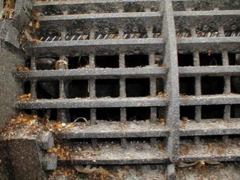
If you have the old style "Low wire" concave, you need to remove every other wire. They are too close together to allow good separation and often plug with soft cob tips in corn. In older machines, it may be necessary to cut them out. On newer machines, one can get a Vice-Grip on a wire and tap the back side of the plier to dislodge the wire.
P3 CAGE
-
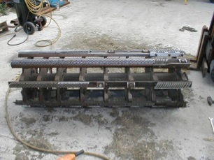
Remove every other wire from separator grate. See note above about shoe overload concerns - same applies here.
-
Obtain a couple F2 rasp bars, part #71142277.
-
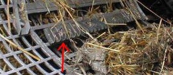
Take the F2 rasp bar and install in bottom of separator grate one next to the threshing section and maybe another next to discharge end to help get the grain out of the wet straw, corn husks, etc. to eliminate cylinder loss.
-
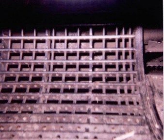
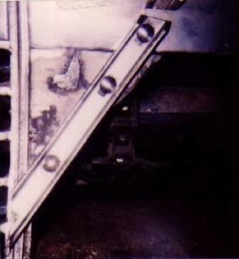
An option for the separator grate if you do have trouble with shoe overload is to cut every other crossbar loose, slide it up to the next one and weld in place (right)
-
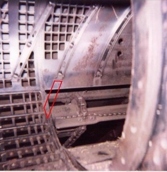
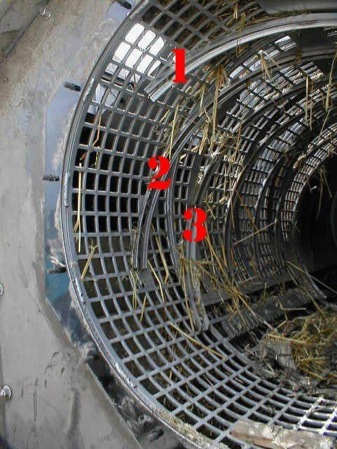
Next, we need to extend that helical over the feeder opening to the cage over into the separation side of cage. On the small P3 (R40/42 R50/52) it is the 2nd helical from the drive end of rotor. On the large P3, it's the 3rd helical. The problem is that this helical drops already threshed crop material back onto the concave resulting in slugging, chewed up straw, broken cobs, and reduced feeding ability. This is a very important mod and should not be overlooked or eliminated!
-
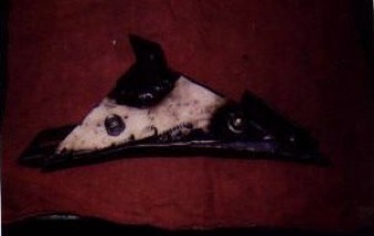
On small P3 machines, cut the crop divider off at the mark that is on it where it bolted to the separator grate. Using a piece of 1/8" flat metal make a triangle piece to cover the hole that will be under the new helical. Using a back-up previously removed from the paddles cut it off to fit under the triangle piece. Then cut the hole in it bigger so you can get the original countersunk bolt head through it. Weld the pieces together, weld the helical to the top of the triangle piece. When you install this in the machine you can drill a hole and bolt in the helical assembly to the combine under the existing helical.
-
Note: It's often a concern that the shoe will overload with this mod. Almost everyone that has done this has NOT had a problem in any crop. The only time it may cause shoe overload is in extremely dry, brittle straw conditions such as very dry windrowed grain.
To do this, remove the crop divider - cut it off to use for bracket to hold helical.
Add helical here. You will also have to add a triangle piece behind the new helical to fill in the gap.
-
On large P3 machines use some 3/16" X 1 1/2" angle make 2 pieces to bolt to holes used by crop divider to support the helical. Then make a triangle piece out of 3/16" plate to cover the hole under the new helical. Then you should be able to get three bolts into the helical, 2 in the triangle piece and one in the combine under original helical. Let the new piece of helical end on the beginning of the separator grate.
-
This is what the mod should look like when completed.
-
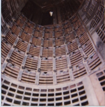
Note: Large P3 only... It may be beneficial to install steep-pitch helicals shimmed closer to the cylinder in the large P3 cages to move crop through faster as shown below.
-
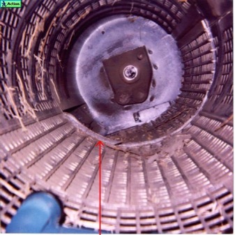
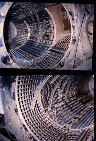
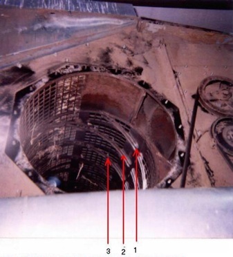
You'll need to extend some helicals into the discharge area to promote smooth straw flow.. There should be 3 helicals in and across the discharge area. These three helicals should be cut off in a stair step fashion to promote even discharge feeding. In the pic on the right, helical #1 which is a short helical, needs to be removed and replaced with a long one that will go up over the top of the cage to the outside edge. Be sure to keep it at least 3" from the "stop sign". Helical #2 may need to be shortened so it stops in the middle of the discharge area. And helical #3 will need a short piece added onto it so it stops just inside the discharge area from the separator area.
-
Be certain to anchor F2 rasp bar securely. Use grade 8 bolts.
-
When completed, your discharge should look like this.
P3 ROTOR
-
Remove rotor from combine.
-
Remove all reverse bars - weld them together to make a new mailbox post!
-
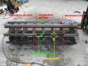
You need to create the "High - Low" effect on the rotor. There are a couple of ways of doing this and they all work so it's your decision as to which path to take. The first way is to create "half-height" bars. They are simply stock forward bars that you grind or cut the teeth down to half their original height. These are installed in rows in the separation section of the rotor and are alternated with full height bars. The high-low concept works in conjunction with the F2 bar(s) installed in separator belly - the half-height bars come around and along with the F2 bars, trip up and flip the crop material over to release trapped grain - all without using additional horsepower like reverse bars are notorious for.
-
Another concept to provide the high-low effect is to remove bars from separation section of rotor and just leave the spot blank. Again, these blank areas allow the F2 bars to trip the crop material up to release grain.
-
It has been suggested to remove two to four FULL ROWS the entire length of the rotor to help prevent cob breakup in corn. However, this configuration occasionally causes problems in green stemmed soybeans.
-
If you wish to have blank rows in the separation section of the small P3's, yet maintain all the bars in the threshing section to aid in getting tough crop material away from the threshing concave, you'll have to cut off about 6" of the middle bars (shown in green below) in the blank rows since the middle bars are shared between the threshing and separating sections.
-
In the above pic, circled in yellow, you can see that in the blank sections we have attached the discharge paddle backup gussets removed when the discharge end of rotor is modified (below). These act as "disrupters" that tear apart any roping or wadding that may occur in tough conditions. The tops need to be ground down about 1/4" to make sure they clear helicals and adjustable separator grate. The leading edges are also sharpened somewhat. Use a grade 8 bolt to hold these on the rotor and tighten very securely!
-
Now we move on to the discharge end of the rotor. In the stock configuration, the discharge paddles extend slightly into the cage - this prevents smooth flow of material into the discharge. As a result, this causes wadding, power consumption, grain loss (trapped in wadding), and rotor rumble. What needs to be done is to cut the stock discharge paddle back and install a short section of fwd rasp. Remove the inner discharge paddle backup gusset (Use as a "disrupter") and bolt section of rasp in this area using the hole the gusset was attached to. Then weld the rasp bar to the discharge paddle. Do this on FOUR rows. On the other four rows, run a rasp bar all the way across the discharge. These mods, in conjunction with the extended helicals into discharge, will allow very smooth crop flow into and out of the discharge. Loewen and Sunnybrook sell kits to do this if you wish to go that route and AGCO sells a "Performance Kit" which is eight part rasp/part paddle bars. If you purchase AGCO's kit, keep in mind that it's highly recommended to still run four full rasp bars across the discharge. These mods can also be seen in the above photos.

